What Goes Into an ILA Hut Build
A complete design and build-out breakdown of an ILA hut, structure, power, cooling, optical equipment, telemetry, and our five-phase delivery process.
By Nate Bruns
ILA (In-Line Amplifier) huts are the unsung backbone of long-haul fiber networks. Every 60–100 km along a terrestrial or submarine cable route, one of these hardened, unmanned facilities keeps the signal alive, amplifying light across thousands of miles without missing a beat. When a data center is decommissioned and routes need rerouting, these huts keep the backbone running.
So what actually goes into building one? Here is the complete picture.
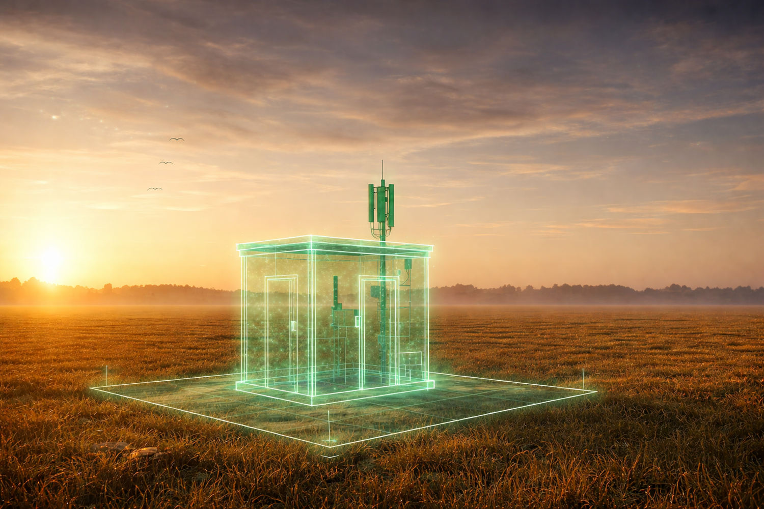
The structure
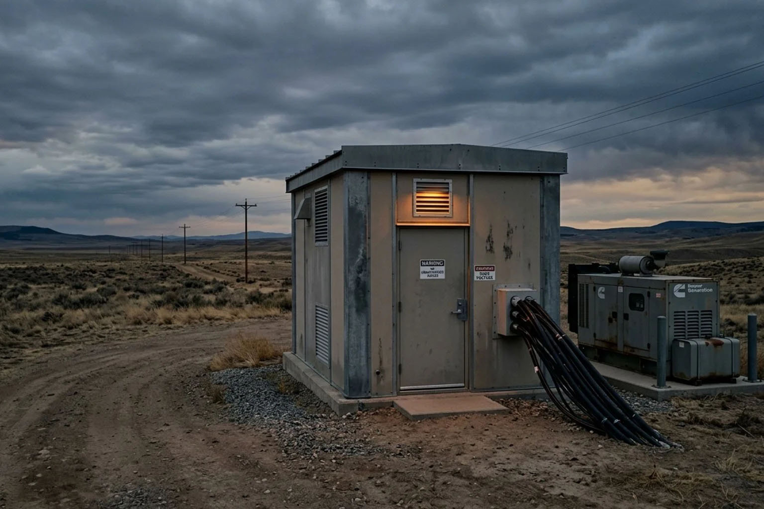
A standard ILA hut is a prefabricated steel or concrete shelter, typically 160–320 sq ft, housing 2–6 equipment bays. Small footprint, but everything inside has to perform reliably for years, in any climate, without regular human presence. Design priorities include weatherproofing and environmental hardening, ratings for local wind and seismic loads, reinforced security with tamper alarms and remote cameras, a poured concrete foundation (often elevated for flood mitigation), hardened conduit runs with pressurized cable vaults, and a vestibule in harsh climates to prevent thermal shock. Every choice traces back to one requirement: this building has to work without anyone in it.
Power
Power reliability is not optional at a remote unmanned site. ILA hut power architecture layers redundancy at every level.
- Utility & transfer. Dual utility feeds from separate paths feed an Automatic Transfer Switch (ATS), if one fails, the other takes over automatically.
- Standby generator. Sized N+1 above the critical load, typically 30–100 kW, with 72–96 hours of fuel autonomy (up to 7 days at remote sites). Status, fuel, run hours, and faults report to the NOC via SNMP.
- –48V DC plant. The industry-standard plant provides 200–600A with N+1 rectifier modules. Battery backup (VRLA or lithium-ion) delivers 4–8 hours at full load, with a Low Voltage Disconnect protecting the strings.
- DC distribution. A main DC fuse/breaker panel distributes –48V to each load, with documented, labeled circuits per bay.
Cooling
Optical amplifiers and electronics are sensitive to temperature swings. ILA huts use DX precision air conditioning in an N+1 configuration, two units, each able to handle the full load, with automatic failover. Target environment: 65–75°F and 40–55% relative humidity. An environmental controller rotates lead and standby units to equalize runtime, and sensors trigger high-temp alarms before equipment reaches shutdown. Hot/cold-aisle principles apply even in 200 sq ft: blanking panels fill unused rack units and overhead trays support front-to-back airflow.
Optical equipment
The whole purpose of the hut is amplification. EDFA (Erbium-Doped Fiber Amplifier) shelves form the core, one shelf per fiber-pair direction, with multiple modules per shelf. Dispersion Compensation Modules install in-line as passive cassettes, and modern deployments may add ROADM shelves for express/add/drop functions. Regeneration sites add transponder and muxponder shelves, WDM mux/demux panels handle wavelengths, and the Optical Supervisory Channel carries telemetry between huts. Fiber distribution panels handle interconnects, slack is coiled in storage spools, and a central Telecommunications Ground Bar bonds every rack and chassis per ANSI/TIA-607.
Telemetry & remote management
Unmanned means monitoring has to be comprehensive. A site controller aggregates alarms; a craft terminal gives technicians local access; an out-of-band management network runs over the OSC wavelength, with cellular or satellite backup. NOC-reported alarms cover door/tamper, smoke and fire, flood sensors, generator state and fuel, rectifier faults, battery discharge and temperature, DC bus thresholds, and fiber-vault pressure. Some responses can’t wait for a call: cooling failover, generator auto-start, and Low Voltage Disconnect all operate autonomously.
Fiber entry & vault
Outside-plant cable enters through hardened, fire-stopped entry ports. Vault fiber is pressurized so a pressure drop signals a sheath breach before it becomes a traffic event. Splice enclosures transition OSP fiber to inside-plant pigtails, and route markers and bonding posts are installed at the perimeter.
Our build process
Decomm Systems uses a phase-gated delivery model refined across hundreds of remote infrastructure deployments:
- Site survey, route walk, geotechnical assessment, utility availability, access logistics, and load calculations.
- Engineering, structural, power, thermal, and optical design packages, with drawing sets and BOMs issued for approval.
- Procurement, shelter fabrication, DC plant, generator, cooling, and optical equipment sourced and staged.
- Build-out, foundation, shelter install, power and cooling integration, rack build, fiber termination and splicing.
- Commissioning, full system testing, alarm verification, NOC integration, and as-built documentation handoff.
Built for the long haul
An ILA hut is a power plant, a cooling system, an optical amplification facility, and a remote monitoring node, all in a 200 sq ft footprint that runs unattended for years. Getting it right takes deep expertise across structural, power, thermal, and optical disciplines, and a delivery process built around precision. That’s what we do.