Racks: The Foundation of Every Data Center
Rack and stack done right is the difference between a data center that hums for decades and one that becomes an operational nightmare. A field guide to the five-phase process, patching, and the principles that matter.
By Nate Bruns
Before a single workload runs, before a cable carries data, before the network breathes, someone has to physically build the infrastructure. That process is called rack and stack, and doing it right is the difference between a data center that hums along for decades and one that becomes an operational nightmare.
What is rack & stack?
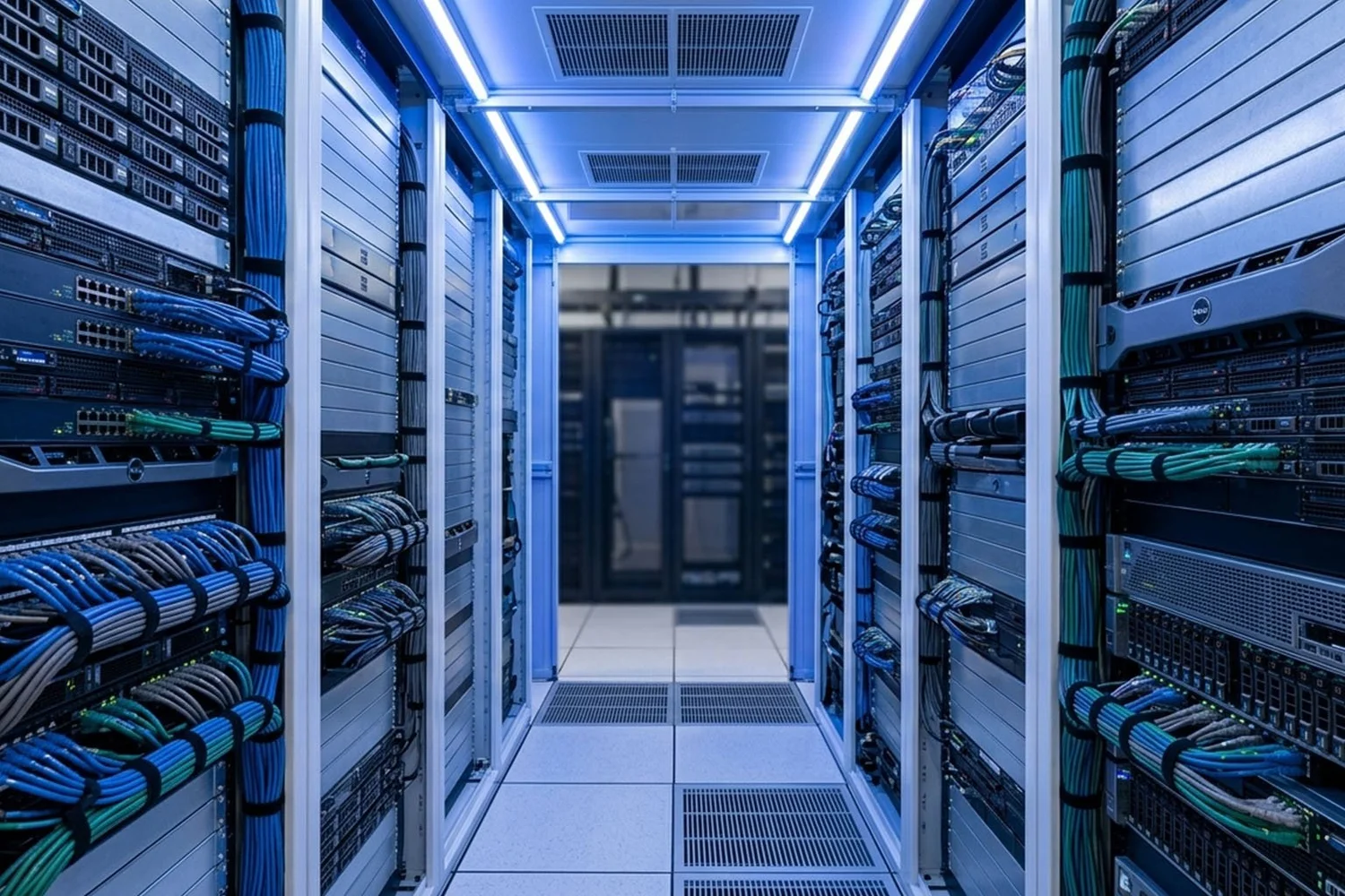
Rack and stack refers to the physical installation of IT equipment, servers, switches, storage arrays, patch panels, power distribution units, into standard 19-inch equipment enclosures. The name is literal: you mount (rack) the equipment and layer (stack) it in the correct order.
Poor decisions compound over the life of the infrastructure. Bad airflow, tangled cabling, and overloaded circuits don’t announce themselves on day one, they surface months or years later, during a maintenance window or a 2 a.m. incident. A data center built right the first time rewards operators with years of clean, efficient operations.
A standard equipment rack is 19 inches wide and measured in rack units (U). One rack unit equals 1.75 inches. A typical floor-standing cabinet is 42U, roughly 73.5 inches of usable vertical space. Every piece of equipment is sized in rack units: servers, patch panels, switches, PDUs, UPS systems.
The five-phase process
Professional rack and stack follows a disciplined sequence. Improvising the order, or skipping steps, creates cable chaos, airflow problems, and equipment that’s nearly impossible to service later.
Phase 1, Planning & documentation
Work begins before anything is unboxed. Technicians review the rack elevation diagram, which maps every device to its assigned rack-unit position. Each device gets an asset tag, an IP or IPMI address, and a port assignment on the patch panel and top-of-rack switch.
Power budgets are verified here. Every device draws a known wattage, and the cumulative load per rack must stay within the capacity of the PDUs and upstream breakers. Overloading a circuit is a common, costly, and entirely preventable, mistake.
Phase 2, Physical installation sequence
Equipment goes in a deliberate order so cables can be managed, airflow maintained, and no component blocks access to another.
- Patch panels go in near the top first, the termination point for structured cabling runs.
- Top-of-rack (ToR) switches follow immediately below, minimizing inter-rack patch-cable length.
- Cable management arms go in next; retrofitting cable management into a full rack almost always compromises airflow.
- Servers and compute are racked top-down within their assigned zone, rail kits first.
- Storage arrays are seated per the controller’s layout map.
- PDUs mount vertically along the rear or sides, redundant deployments use two PDUs per rack on separate A-side and B-side circuits.
- UPS units, when local to the rack, go at the bottom due to battery weight.
- Blanking panels fill every unused rack unit, an airflow decision, not a cosmetic one.
Without blanking panels, hot exhaust recirculates from the hot aisle back through empty rack space into the cold-aisle intake, raising inlet temperatures and driving up cooling costs.
Phase 3, Power cabling
Power cables run from each device to the appropriate PDU outlet. In a well-designed deployment they’re color-coded, black for A-side, gray or white for B-side, so it’s immediately obvious whether dual-corded devices are correctly split across independent circuits. Lengths are matched to reach the outlet with minimal slack; bundled excess power cable is an underappreciated cause of restricted airflow.
Phase 4, Network cabling & patching
With power verified, network cables are run and patching begins. This is where the quality of the entire deployment becomes most visible (see patching, below).
Phase 5, Labeling & documentation update
Every port, cable, device, and rack position is labeled. Port labels match the patch-panel schedule, asset tags are associated with rack positions in the DCIM system, and the rack elevation diagram is updated to reflect the as-built state. This documentation becomes the system of record for every future move, add, or change, and it needs to be accurate from day one, not reconstructed from memory after the fact.
Patching
Patching is the act of connecting equipment ports using structured cabling, copper (Cat6A, Cat6) or fiber (OM4, OS2), through patch panels. Done correctly, it creates a clean, traceable, serviceable network. Done sloppily, it creates a dense, unmanageable mess.
Patch panel architecture
Patch panels serve as the permanent termination point for horizontal cabling runs. Instead of running long cables directly from a server NIC to a switch port, the infrastructure is split: a fixed structured cabling run from patch panel to switch, and a short patch cable from the panel’s front port to the device. When a server needs a different switch port, only the short patch cable moves. This "moves, adds, and changes" (MAC) philosophy is the foundation of maintainable network infrastructure.
Naming conventions
Every port should follow a consistent scheme that encodes the location hierarchy into the label, for example, DC1-ROW-C-RACK-04-PP-01-P12 decodes as Data Center 1, Row C, Rack 04, Patch Panel 01, Port 12. When a technician is tracing a fault at 2 a.m., that label is the difference between a five-minute fix and a two-hour war story. Port-to-port connectivity lives in a cable schedule mapping each cable’s A-end to B-end, type, length, and color.
Fiber: polarity and end-face cleanliness
Fiber adds a concern copper doesn’t: polarity. The transmit fiber of one device must reach the receive port of the remote device, get it wrong and the link simply doesn’t come up, with no error message pointing to the cable. End-face contamination is the leading cause of fiber link failures; a single fingerprint on an LC connector can attenuate a signal enough to drop the link at higher rates. Every connection should be cleaned with a one-click cleaner and inspected with a fiber inspection probe before insertion.
Cable dressing
Patch cables should be dressed, organized, routed cleanly, and secured, not plugged in and left to sprawl. Respect bend radii, especially for fiber (minimum 30mm). Cable length matters more than most people think: a 10-foot cable where a 3-foot would work creates slack that blocks airflow and complicates service. Stock standard lengths and select the shortest cable that reaches with a 6–12 inch service loop.
The principles that separate good deployments from costly ones
- Airflow first. Design cold-aisle/hot-aisle containment before a single server goes in. All equipment faces the same direction; blanking panels in every empty U.
- Document as you go. Update asset tags, port schedules, and elevation diagrams the moment a cable is seated, not after the fact.
- Redundancy by design. Dual power (A/B), dual NICs on separate switches, and redundant cooling paths must be designed in from the start. Retrofit redundancy is expensive and disruptive.
- Label everything. Both ends of every cable, every port, every device, every outlet. If it isn’t labeled, it effectively doesn’t exist.
- Right cable, right length. Match cable type to link speed and distance, use the shortest patch cable that fits, and avoid coiling excess.
- Inspect fiber connectors. Clean before every connection and inspect with a probe, a non-negotiable step.
The long game
Rack and stack is physical, methodical, and detail-intensive, but its effects persist for years, sometimes decades. A data center built with discipline, careful documentation, and thoughtful cable management is one operators can actually work in, that absorbs growth, and that doesn’t generate a constant stream of avoidable incidents.
The opposite is also true. Data centers built in haste, without standards, documentation, or attention to airflow and power redundancy, become burdens. They resist change, hide faults, and create technical debt that compounds with every new device.
The rack is where the data center begins. How well it begins determines everything that follows.
Related resources
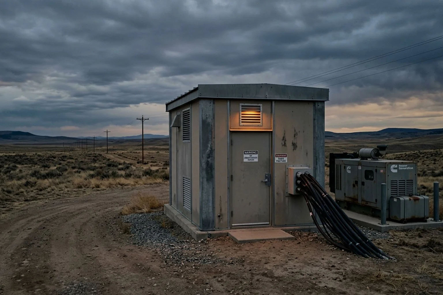
What Goes Into an ILA Hut Build
A complete design and build-out breakdown of an ILA hut, structure, power, cooling, optical equipment, telemetry, and our five-phase delivery process.
Read more →
AI Is Fueling a Surge in ILA Hut Demand
AI workloads are driving record demand for in-line amplifier huts. Here is why ILA huts have become critical infrastructure for next-generation networks.
Read more →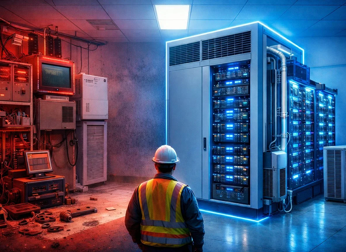
Unlock AI Capacity Without Building a New Data Center
Decommissioning legacy infrastructure can free up power, cooling, and space for AI workloads, without the multi-year wait of a new build.
Read more →